DH Convention
To determine the position of a point in space, we typically construct a coordinate system (reference frame) and specify the point’s location using $(x, y, z)$ coordinates relative to the origin. However, for robots or robotic arms with multiple rigid bodies, directly using a single unified coordinate system becomes complex. After numerous joint movements, determining positions requires extensive geometric calculations. To address this, previous researchers developed clever methods, including the DH (Denavit-Hartenberg) convention introduced in this article. This method also has a modified version, but this article focuses solely on the Standard DH convention—a method for constructing reference coordinate systems for mechanical systems connected by joints. Its core principle involves establishing coordinate systems for each rigid body based on joint information, obtaining relevant parameters to construct transformation matrices (discussed below), and thereby determining the position information of each rigid body in the base coordinate system.
As mentioned above, the DH convention follows these steps to obtain coordinate systems for each rigid body in a mechanical system:
- Set the axis direction of the $(i+1)$-th joint as the $z_i$ axis of the coordinate system of the rigid body (for rotational joints, the rotation direction is the $z_i$ axis; for prismatic joints, the extension direction is the $z_i$ axis);
- The $x_i$ axis of the rigid body’s coordinate system must be perpendicular to both the $z_{i-1}$ and $z_i$ axes, with their extensions intersecting both axes (the direction is generally from the $z_{i-1}$ axis toward the $z_i$ axis);
- After determining the above two axis directions, the $y_i$ axis of the rigid body’s coordinate system is determined by the right-hand rule.
Relationships between $xyz$ coordinate system, the right-hand rule, and RGB colors
- Relationship between $xyz$ coordinate system and right-hand rule: $x$, $y$, and $z$ are represented by the thumb, index finger, and middle finger of the right hand respectively, with positive directions from the palm toward the fingertips;
- Relationship between $xyz$ coordinate system and RGB colors: $x$, $y$, and $z$ are represented by red (R), green (G), and blue (B) respectively.
In the following example, based on the DH convention introduced, the coordinate system of the $i$-th rigid body (link $i$ in the diagram) can be inferred as follows:
- Since this joint is a rotational joint, its $z_i$ axis is the rotation direction, which is the rotation center;
- When determining its $x_i$ axis, we must utilize the $z_{i-1}$ axis of the previous rigid body (the prismatic joint labeled as Joint $i$ in the diagram, whose vertical extension direction is the $z_{i-1}$ axis) and the current $z_i$ axis. By constructing a perpendicular relationship, the $x_i$ axis can be obtained;
- Finally, using the right-hand rule, place the middle finger and thumb on the already-determined $z_i$ and $x_i$ axes respectively; then the $y_i$ axis direction is determined by the index finger.
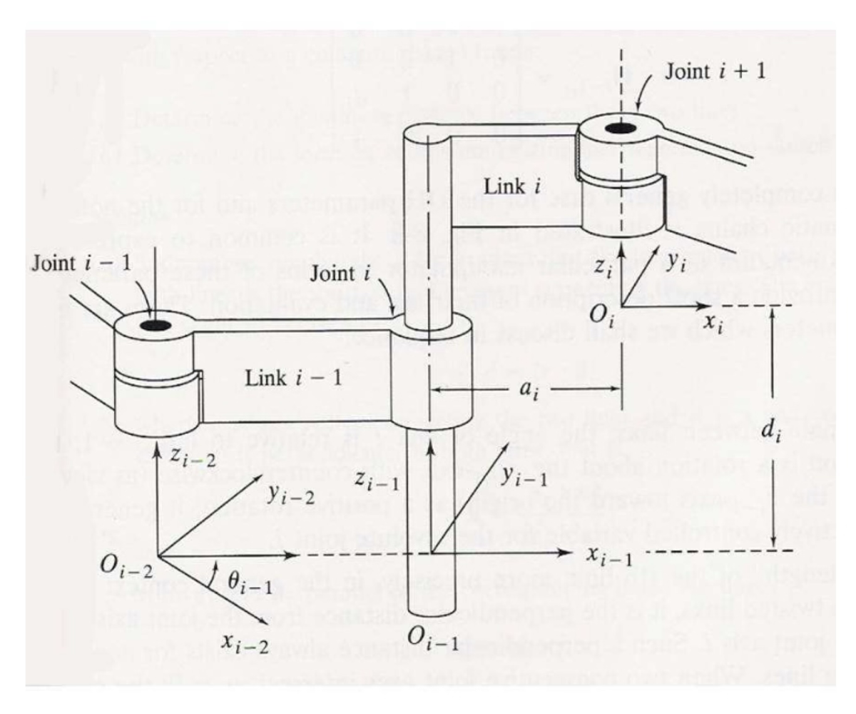
Through the above example, we can understand the steps of the DH convention and obtain the required coordinate system. Refocusing on the goal of constructing coordinate systems to obtain spatial information of target rigid bodies, we have only obtained information of each rigid body in their respective coordinate systems. To obtain the position and orientation information of the end-effector relative to the base coordinate system, we need to collect additional information: DH parameters and transformation matrices constructed based on these parameters. DH parameters describe the relationship between two rigid bodies connected by the same joint; for instance, the distance of a link in the diagram can be viewed as the offset distance of one coordinate system relative to another. Due to the presence of rotation angles, the actual situation can be more complex. We now provide the required DH parameters, with detailed explanations on how to use these parameters in future articles:
- Joint offset distance $d_i$ (for prismatic joints only): as shown in the diagram, the distance along $z_{i-1}$ between $x_{i-1}$ and $x_i$;
- Joint angle $\theta_i$ (for rotational joints only): as shown in the diagram, the angle $\theta_{i-1}$ between $x_{i-2}$ and $x_{i-1}$ after rotation along $z_{i-2}$;
- Link length $a_i$ (such as the length of a link): generally the distance along $x_i$ between $z_{i-1}$ and $z_i$;
- Link twist angle $\alpha_i$: generally the angle formed between $z_{i-1}$ and $z_i$ after rotation along $x_i$.
Based on the collected parameters, the relationship between two rigid bodies can be expressed as a matrix operation:
$$ A_{i-1}^i = Rot(z, \theta_i)Trans(0, 0, d_i)Trans(a_i, 0, 0)Rot(x, \alpha_i) $$where $Rot(z, \theta)$ and $Rot(x, \alpha_i)$ are rotation matrices, and $Trans(0, 0, d_i)$ and $Trans(a_i, 0, 0)$ are translation matrices. The construction and meaning of these two matrices will be detailed in the article on Homogenous Transformation Matrix.